The inductor is from one old PC power supply I had, you can salvage one from a old PC power supply. A 15A or 10A diode bridge will be fine too. It won't be too difficult for you to find one like mine, just search for "diode bridge 25A" on eBay. You can calculate the maximum output with the formula: ((Vout transformer * 1.41) - 3,4).Ī 25A diode bridge, that I have bought on a local hardware store, was used. It will only change your maximum output voltage. You can use a transformer from 12 to 24 volts/5 amp. The 500ohm resistor between the 2N3055 emitter and base is for it don't lose its base-emitter referential, the power supply would work without it, but less stable.įor filtering a 10000uf/50V capacitor was used because it was laying around at my home, but you can use a 4700uf/50V capacitor, just remember to modify the PCB. The 500ohm potentiometer I added on LM317 feedback is to adjust the maximum output. (I used a 0,33ohm because I already had them at home.) The two 0,22ohm resistors on 2N3055 emitters is for ensure that both of them work together preventing one outputting more current than the other leading them to burn.

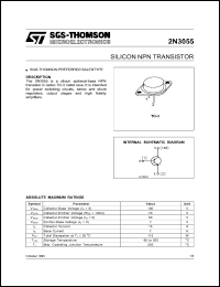
The LM317 controls voltage and the 2N3055 supplies current. So, this is the basic function of the circuit. This starts happening when the IC LM317 is outputting 73mA, as ohm's law show us: 0,6/8,2 = 0,073.Ī easier way to understand it is that the two transistors will start to "help" the LM317 with current, while the LM317 adjusts the voltage. The 2N3055 is on a emitter follower configuration and it will supply current to the output of the power supply. When this voltage drop is higher than 0,6 volts, the TIP42C starts to conduct and it drives the two 2N3055.

As current starts to flow through the 8,2ohm resistor, a voltage drop will appear across it. The way the circuit works is very easy to understand.


 0 kommentar(er)
